The architecture of the DevOps Modeling Platform covers a wide set of technologies that can be divided in two groups: the DevOps Modeling Platform components and the Eclipse Components.
Provided here is a brief overview of each component playing a role in RMP's programming model. We will present these components using a bottom-up approach.
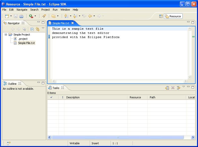
Central to the Eclipse technology is the "Eclipse Platform". This component includes frameworks to build user interface, manage resources, coordinate builders, integrate debugger and much more. The following screenshot shows the Eclipse workbench as provided by the Eclipse Platform, without the IBM Model RealTime product installed:
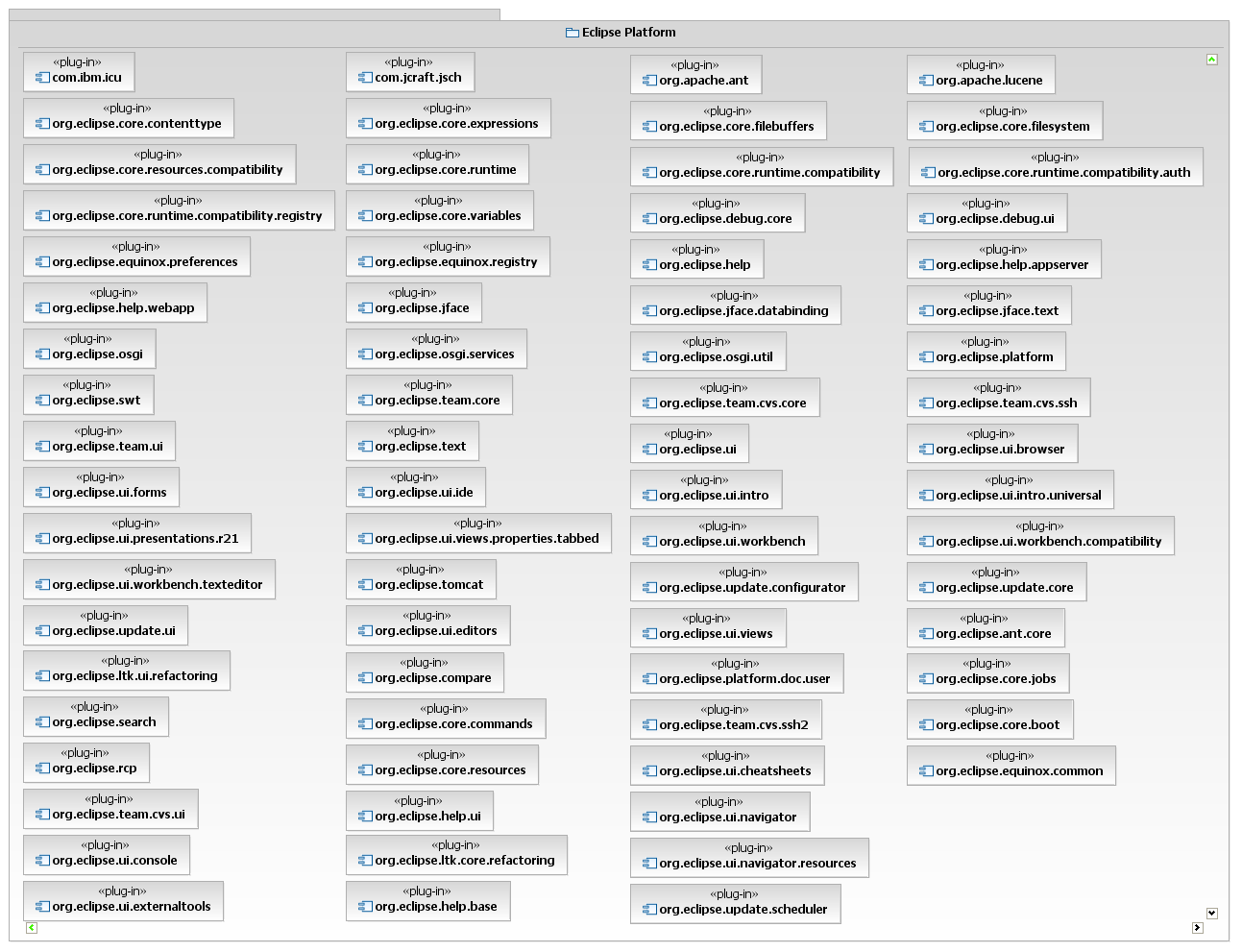
A major architectural feature of Eclipse is its ability to be extended by components called 'plug-ins'. A plug-in usually bundles Java code, resources and manifest files. The Eclipse platform in itself is a set of plug-ins. The DevOps Modeling Platform also consists of plug-ins. Extending IBM DevOps modeling solutions is done through plug-ins as well. Below is a component diagram presenting some of the Eclipse Platform plug-ins:
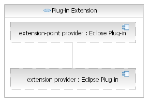
To enable integration, Eclipse introduces two concepts: extension-point and extension. A plug-in that offers other plug-ins to extend its functionality defines an extension-point in its plug-in manifest file. A plug-in willing to extend an extension-point defines an extension in its plug-in manifest file.
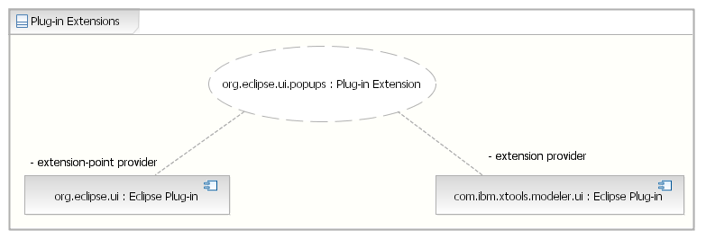
The Eclipse Platform plug-ins define a set of extension-points. As an example, the platform plug-in named
org.eclipse.ui defines an extension point called org.eclipse.ui.popupMenus that other plug-ins
such as com.ibm.xtools.modeler.ui from the DevOps Modeling Platform can use to contribute context menus.
The Eclipse Platform is not the only Eclipse technology that the DevOps Modeling Platform leverages. The following diagram presents some of these other Eclipse components and their dependencies:
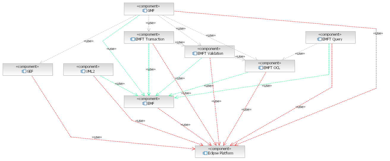
Using a bottom-up approach, we will briefly introduce how the DevOps Modeling Platform leverages these technologies.
The Eclipse Platform, which we introduced earlier, is responsible for all the basic frameworks required by an integrated development environment. IBM DevOps modeling solutions make great use of the extensibility offered by the platform to offer editors, views, menus, help, etc... It is possible to extend these solutions using the frameworks of the Eclipse Platform.
Here are some examples of capabilities you can extend:
For more information about how to extend the Eclipse Platform, see the Platform Plug-in Developer Guide
EMF is a model integration technology and serves as the backbone to IBM DevOps modeling solutions. The framework is composed of runtime and tooling components.
Unlike UML models, which are instances of
the UML metamodel as defined by the OMG; EMF models
are instances of the Ecore metamodel, defined by the EMF project. By design, Ecore is much simpler than UML since
it focuses solely on the structural aspect of modeling. EMF models are also referred to as Ecore models
and are generally persisted with filename whose extension is .ecore
EMF's tooling components include a rudimentary editor to help create Ecore models. Also included are tools that can generate an Ecore model from various sources such as from an XML Schema, from annotated Java files, from a UML2 model or from a model created in IBM Model RealTime.
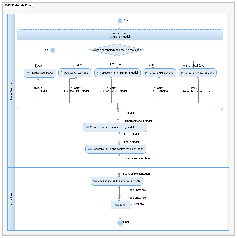
Another feature of EMF's tooling is the ability to generate the Java implementation of an Ecore model. This implementation enables the creation of instances of the given Ecore model, we call these EMF instance models. The default generated implementation serializes these model instances in XMI, provides on-demand resolution of cross-model references, provides reflection API, and includes Eclipse integration through a simple editor and a creation wizard.
The following activity diagram presents the workflow going from the creation of an Ecore model by a model designer to the serialization of an instance model of that Ecore model by a model user.
The generated implementation requires the EMF runtime, which among other things, contains various base classes and interfaces. The most important of these being EObject, the mother of all EMF objects.
The DevOps Modeling Platform makes heavy use of EMF. The implementation of the models the platform manages must be based on the EMF runtime.
Ecore models can be transformed into IBM Model RealTime models using File > Import > Modeling > Ecore Model. The reverse is also possible by using File > Export > Modeling > Ecore Model or File > New > Eclipse Modeling Framework > EMF Generator Model and then picking the IBM Model RealTime model model importer.
For more information about the Eclipse Modeling Framework, see the EMF Documentation web page.
UML2 is an EMF-based implementation of the UML Superstructure specification.
The component includes the implementation of the UML 2.0 metamodel generated by EMF as well the rudimentary Eclipse editor and wizard also generated by EMF.
UML models are generally persisted with filename whose extension is .uml.
Note that when we refer to the OMG specification, we refer to UML 2.x. Notice the space between UML and 2.x. We refer to the Eclipse technology implementing the specification as UML2, without space.
The DevOps Modeling Platform leverages this implementation for its UML functionality. However, because its UML models
also include diagram specific information, the platform persists its UML models using the .emx extension
instead of UML2's .uml.
UML2 models can be transformed into IBM Model RealTime models using File > Import > Modeling > UML 2.2 Model. The reverse is also possible by using File > Export > Modeling > UML 2.2 Model.
For more information about the UML2 APIs, see the UML2 Developer Guide.
EMF OCL is an EMF-based implementation of the OCL 2.0 specification. The component includes the implementation of the OCL Abstract Syntax metamodel generated by EMF, parsers for concrete syntax expressions, as well as an engine to evaluate OCL expressions (abstract or concrete) against any EMF instance model.
The DevOps Modeling Platform uses EMF OCL to evaluate OCL expression for the models it manages as well as to validate user input during code completion.
For more information about the EMF OCL component, see this article.
EMF Validation is an extensible validation framework for EMF instance models. The framework allows plug-ins to contribute constraints to instance models of a given Ecore model. These constraints can be described in any language plugged into the framework. Out-of-the-box support exists for Java and OCL.
The DevOps Modeling Platform uses EMF Validation to constrain the models it manages. In particular, it uses the framework to constrain UML2 models according to the official specification.
For more information about the EMF Validation component, see the EMF Validation Developer Guide.
EMF Transactions enhance the model management offered by EMF by providing a transactioning API which enables:
The DevOps Modeling Platform uses EMF Transactions for all of its model management. Integrating with IBM DevOps modeling solutions requires client plug-ins to use the EMF Transactions API to access and modify models. Alternatively, some frameworks built over EMF Transactions such as the Graphical Modeling Framework (GMF) offer other API that can be used instead.
For more information about the EMF Transactions component, see the EMF Transactions web page.
EMF Query is a framework to help traversal of EMF model instances. It provides an SQL inspired set of classes to formulate queries as well as a rich Condition classes hierarchy. OCL expressions are supported to act as filters during model traversal.
The DevOps Modeling Platform uses EMF Query to perform searches within the models it manages. Because traversing a model can be an extremely costly operation, the platform will generally leverage its own indexing framework instead to query for references and attributes that it knows are indexed.
For more information about the EMF Query component, see the EMF Query web page.
GEF provides the basis for the creation of graphical editors. It includes a model-view-controller (MVC)-based framework as well as a rendering subsystem called Draw2d.
The MVC model represents the "data" to be rendered. GEF does not impose restrictions on the implementation technology; noteworthy is that it does not require the model to be an Ecore model instance. The only requirement for the model is that it supports some sorts of notification mechanism. The MVC View is responsible for the rendering. It is implemented by Draw2DFigure objects or
SWT TreeItem objects.
Finally, the MVC controller is responsible for tying the figure and the model. It responds to model notifications and update
figures or tree items accordingly. The controller is implemented by GEF
EditPart
objects which also manage a set of objects responsible for the behavior aspect called
EditPolicy.
The DevOps Modeling Platform uses GEF indirectly for its diagram implementation through the GMF component.
For more information about GEF, see the GEF Programmer's Guide
GMF is a framework to create graphical modeling editors. It consists of two main parts, a runtime component and a tooling component. The runtime provides the infrastructure required to support extensible and feature rich modeling diagram editors based on GEF and EMF. The tooling enables the generation of such editors from various input models.
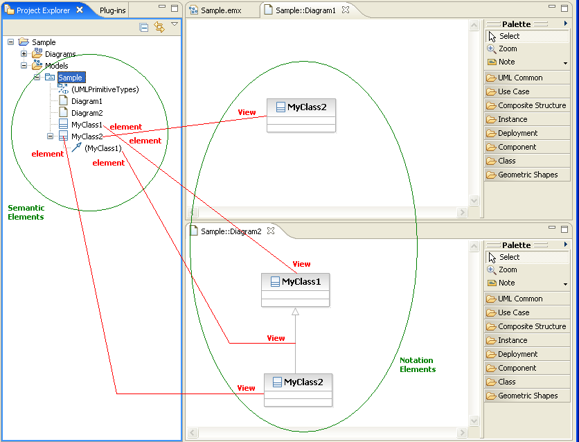
The GMF Runtime follows the same MVC pattern used by GEF. However, in GMF the MVC model role is played by two models:
The notation model View
class is the basis for every visible element on a diagram. One of the main features of a View is its optional reference to
an object from the semantic model. This reference, called element, refers to the non-visual semantic element the view
represents.
Through plug-in extensions, the GMF runtime makes GEF extensible by enabling third-party plug-ins to participate to the various aspects of a diagram's lifecycle. Here is an overview of the capabilities that can be extended:
The DevOps Modeling Platform uses the GMF Runtime extensively. In fact, the runtime was originally the DevOps Modeling Platform diagram runtime which was contributed to the GMF project. Because every of its diagrams are based on this runtime, the above extensibility is now available for DevOps modeling solutions.
GMF's tools enable the rapid creation of domain specific modeling editors to complement the editors provided as part of IBM DevOps's modeling solutions. Thanks to the fact these editors leverage the same runtime the DevOps Modeling Platform leverages, users of these domain specific editors will enjoy the same user experience. This considerably decreases the learning curve associated with new domain specific modeling editors.
The editors generated using GMF can take advantage of the various services offered by the DevOps Modeling Platform, including:
It is also possible to integrate GMF generated diagram editors within IBM DevOps Modeling solutions' diagrams. Clear instructions can be found in Integrating GMF Generated Editors.
For more information about GMF, see the GMF Developer Guide
In remainder of this programmer's guide, unless specified otherwise, the term GMF refers to the Runtime component of GMF, as opposed to the tooling component.
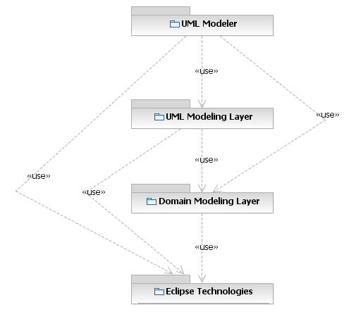
RMP is made of 3 layers: UML Modeler, UML Modeling Layer, Domain Modeling Layer.
The UML Modeler layer includes the classes and interfaces required to manage the platform's UML Modeler.
The
UMLModeler
class is the entry point to control the lifecycle of the modeler's UML models and profiles. As well, it provides access
to various classes required to interact with UML models.
The UML Modeling Layer includes helpers to work with UML models and diagrams.
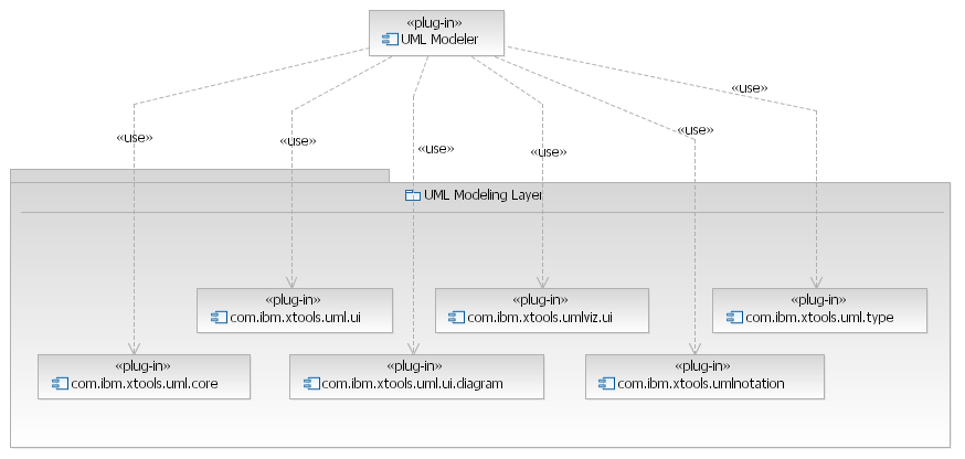
Below is a summary of each components of the UML Modeling Layer:
com.ibm.xtools.uml.core
- Includes helpers to find UML objects in modelscom.ibm.xtools.uml.type
- Includes helpers to use UML ElementTypescom.ibm.xtools.uml.ui
- Includes helpers to select UML objects or to retrieve them as well as a
specialization
of GMF's Element Selection service that better handles concurrencycom.ibm.xtools.uml.ui.diagram
- Includes helpers to find, create, customize or analyze diagramscom.ibm.xtools.umlnotation
- Includes an extension of GMF's Notation model which supports UML specific stylescom.ibm.xtools.umlviz.ui
- The main entry point to managed the lifecycle of diagram files (.dnx) with UML contentThe Domain Modeling Layer includes various services useful for the production of arbitrary EMF-based modeling editors. It includes the following components:
com.ibm.xtools.emf.core
- Provides migration support for Ecore instance models based on an old version of their Ecore metamodel as well as support for
the addition of signatures to model filescom.ibm.xtools.emf.index
- Provides indexing support for Ecore instance models, enabling the rapid execution of model queries on open and close models.com.ibm.xtools.mmi - Enables metamodel integration (MMI) by providing a framework for mapping model instances from a non EMF-based domain to an EMF-based metamodel.
MMI supports visualization of elements of the source domain in diagram editors of the target domain. The framework also supports the synchronization
of changes performed in either the source or the target domain