The diagrams managed by the platform are based on the GMF Runtime. They are instances of the latter's
notation model, which is an Ecore model. The UML Modeling Layer of the DevOps Modeling Platform
introduces its own UML specific notation model that extends GMF's. The notation model defines a
Diagram
object that represents any diagram. A diagram is either owned by a resource or owned by a model element.
When owned by a resource, the notation model instance describing the diagram is persisted in an RMP
Diagram Resource file (.dnx).
UMLDiagramResourceUtil
offers various utilities to manage such diagrams.
When owned by an element, diagrams are added as an annotation to these
elements and are persisted in RMP's UML Modeler files (.emx).
IUMLDiagramHelper.createDiagram()
is a helper to create such diagrams.
IUMLDiagramHelper.getDiagrams()
is used to retrieve the list of diagrams owned by a given UML2 Namespace element.
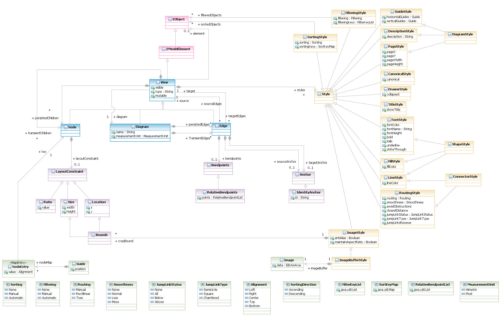
The GMF notation model provides the basic objects required to describe diagrams. The model can represent diagrams from arbitrary domain, it is independent of UML. The following class diagram presents the various notation objects:
A Diagram object is a View that contains all the visible top-level
Nodes of a diagram as well as every Edges.
Node, Diagram and Edge are Views, this involves they can have children Nodes, they can be the source and/or
target of an Edge, and they can own Styles.
Styles are optional properties of a View. Most Styles are only useful to specific Views, for instance
FillStyle has not effect when applied to an Edge. Views inherit from
EMF's EModelElement,
which grant them all EMF object privileges as well as the ability to be annotated.
Element is an important property of a View. It references the domain element the view represents, if any.
The element is an EMF Object. When a View is purely notational, or is nested within a top-level Node, the
Type property is generally used to distinguish the kind of the View.
A detailed explanation of each object of the notation model is available in the source code of the
org.eclipse.gmf.runtime.notation package.
The UML notation model extends the GMF notation model. It extends the styles defined in GMF for UML specific concerns.
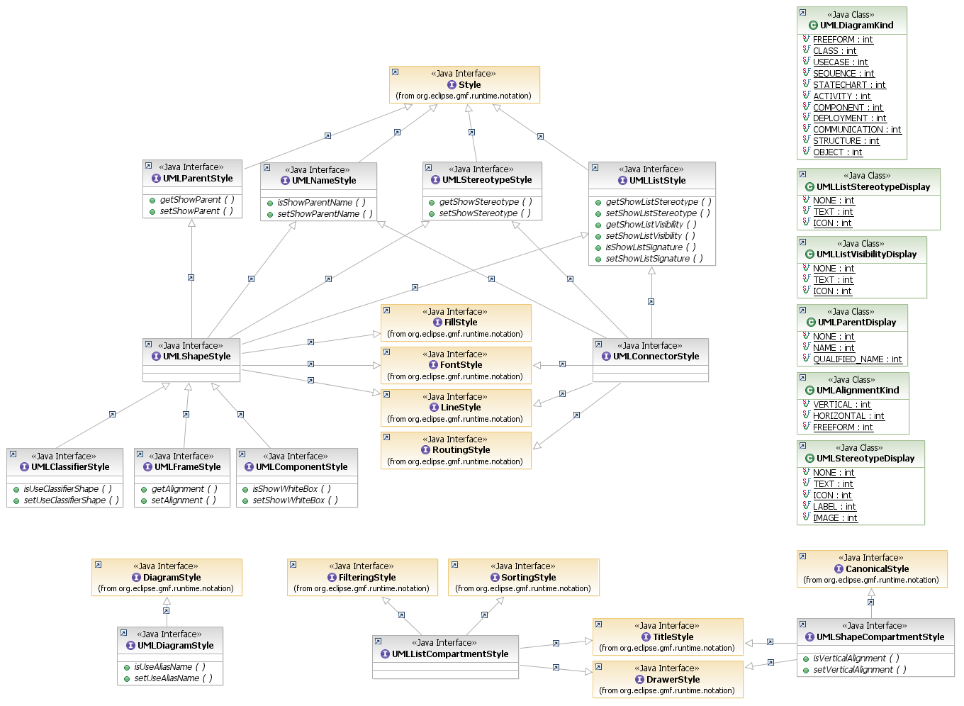
A detailed explanation of each styles of the UML notation model is available from the
com.ibm.xtools.umlnotation package documentation.
IUMLDiagramHelper.getDiagrams(),
IUMLDiagramHelper.createNode() and
IUMLDiagramHelper.createEdge() API calls. The example below demonstrates how to create a simple class diagram.
        // Create a freeform diagram
        IUMLDiagramHelper dgmHelper = UMLModeler.getUMLDiagramHelper();

        Diagram dgm = dgmHelper.createDiagram(model, UMLDiagramKind.FREEFORM_LITERAL);
        dgm.setName("Freeform Diagram");//$NON-NLS-1$

        Class class1 = model.createOwnedClass( "Class1", false);//$NON-NLS-1$
        Interface interface1 = model.createOwnedInterface("Interface1");//$NON-NLS-1$
        InterfaceRealization iRealization = class1.createInterfaceRealization(null, interface1);

        Node nClass1 = dgmHelper.createNode( dgm, class1 );
        Node nInterface1 = dgmHelper.createNode( dgm, interface1 );
        Edge irEdge = dgmHelper.createEdge(nClass1, nInterface1, iRealization);
        dgmHelper.openDiagramEditor(dgm);
        dgmHelper.layout(dgm, LayoutType.DEFAULT);
Some kinds of diagrams known as "machine diagrams", however, will create the diagram automatically. Machine diagrams are the UML activity, composite structure, sequence and statemachine diagrams. Unlike typical diagrams in which nodes are children of the diagram, machine diagrams only have a single child node - the FRAME. The FRAME node will contains at least one COMPARTMENT which will contain nodes as shown in the following figure:
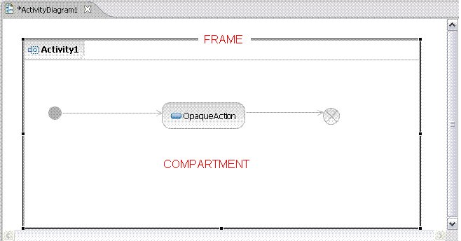
The typical machine diagram node structure would look like the following:
Diagram
  +- Node  (FRAME)
         +- Node  (COMPARTMENT)
             + Node-1
             + Node-2
             + Node-N
        IUMLDiagramHelper dgmHelper = UMLModeler.getUMLDiagramHelper();
        dgmHelper.openDiagramEditor( dgm );
        View frame = (View)dgm.getChildren().get(0); // frame
        View compartment = (View)frame.getChildren().get(0); // main compartment
A better approach is to use the
IUMLDiagramHelper.getChildView(View container, String type)
API. This call retrieves a child node using its type.
The following table defines the list of types and the nodes they represent for the various machine diagrams.
view.getElement() instanceof org.eclipse.uml2.uml.Regionview.getElement() instanceof org.eclipse.uml2.uml.Interaction
The following code example could be used to access the activity frame and activity compartment from the activity diagram shown above:
	IUMLDiagramHelper dgmHelper = UMLModeler.getUMLDiagramHelper();
	dgmHelper.openDiagramEditor( dgm );
	View af = dgmHelper.getChildView( dgm, "Activity Frame"); // frame
	View ac = dgmHelper.getChildView( af, "ActivityCompartment"); // main compartment